RESEARCH BACKGROUND
In the last decades, GNSS navigation has been much improved, compared to survey-grade equipment, low-cost devices performance is not satisfied market demands. Many particular scenarios such as offline shopping or open-air parking need high accuracy positioning.
Because the raw GNSS data is unavailable, prior researchers can only use external receiver to connect to smartphone antenna and chips separately to demonstrate the phone enable to achieve high-accuracy positioning. Until 2016 google release the Nougat OS and provide the GnssMeasurement and GnssClock classes, that means it will be possible to realize high-accuracy position algorithm on a stand-alone smartphone platform.
Compared to the professional receiver better sensitivity and multipath suppression, smartphone antenna easily affected by signal direction especially muti-path signal. What’s more, if we don’t want to establish the atmosphere error model (its so trouble in phone), the ionosphere and troposphere would result us dozens of meters position error.
For meter-grade precision positioning, the widely application is to make use of Wi-Fi signals with predetermined database, but the ideal solution is employing smartphone original GNSS data and sensors such as inertial measurement unit(IMU). In our work, we just use smartphone IMU to assist our system.
II. PDD model and imu integration scheme
Traditional pseudorange single point use least square(LS) algorithm, the biggest problem of LS in smartphone is LS needs multi- iterations, it will lead huge amount of calculation and the LS result is not smooth, so this algorithm maybe suit for position but not navigation. Kalman filter is suitable to be considered.
So, kalman filter is needed,There are three problem left:
1.Traditional Kalman filter was only for linear control system, direct single point positioning is no longer a linear process, we should use extend kalman filter to solve it.
2.Ionosphere and troposphere errors are still in the model.
3.Rover baseline direction vector Ir stability is unreliable especially the Ir was generated by smartphone, the position value is coupled with velocity.
Based on short baseline hypothesis, the Rover baseline direction vector can be regard as parallel lines. Ionosphere and Troposphere were ignored in short base-line which no longer than 10km. Further, rur can be equal to -bur·Ir. this step avoids to linearized the estimation,, extend kalman filter is no more needed and the position is decoupled with velocity because the direction vector Iu is no more determined by user.
Smartphone clock error is an unstable factor, the quality of clock will subsequently analysis in next chapter. Thus we adopted double difference to eliminate smartphone clock error. For exchange, RTD will sacrifice one equation in observation, 5 visible satellite is essential.
To make the kinematic position solutions converge well, we also explored an assisted RTD method to update velocity states by using MEMS-based IMU. IMU high credibility in short time means that it is an ideal complementary with GNSS system, IMU can continously provide high update rate while GNSS update rate is 1HZ. IMU generally exists a fixed bias for every time the power on. As the figure depicted that if only rely on IMU, the fixed bias will Rapidly producing large drift. According to experience, the zero bias value of accelerometer would be fixed down after every power-on, so zero bias only need to be calculated one time, and one minute is enough if we only need zero bias.
Consumer-grade MEMS-based IMU always suffered from system instability and oscillation noise, system instability refers to no accurate scaling, sensor axis misalignment and cross-axis sensitivities. A direct time-domain-analysis technique of IMU noise is Allan variance Model which pointed out the representation of IMU noise terms: quantization noise, angle(velocity) random walk, bias instability ,rate random walk and drift rate ramp. By integrating the IMU in the fusion algorithm, these error will be accumulated, leading to a significant drift in the positioning result. According to experience, the zero bias is the main factor should be considered for accelerometer, although zero bias instability is hard to evaluated every time, the zero bias value of accelerometer would be fixed down after every power-on, thus zero bias only need to be calculated one time, and one minute is enough if we only need zero bias.
The KF filtering initial value was obtained by least-squares (LS) estimation. Although the initial value has little effect as the time of KF iterations increases, the appropriate and correct initial value is conducive to fast convergence. As all equations variables are linear in difference LS model, there is no iteration during LS calculation. Therefore, a large observations error in LS matrix may produce destructive result, an empirically elevation cut-off angle was set to 15 degree, besides the threshold we set in data collection process.
A precise observation should have higher weight and more credibility than other imprecise ones. Thus weighted least squares(WLS) should be adopted, according to Gerdoan paper, schemes of CNR-based weighted and Elevation-based weighted or combination weighted are no significant differences, so we choose CNR-based weight scheme to reduce the amount of calculation. Residual-based RAIM to perform consistency checks was induced to strengthen the system robust and set the max displacement between every two epochs no exceed 20 meters.
The main differences between direct single point and IMU-assisted double difference model are as follows:
- Limited by smartphone clock oscillator quality, smartphone GNSS chips clock error drift dramatically affects system stability, PDD can eliminate the clock error of smartphone and satellite which reduce the system instability and the noise parameter estimator numbers.
- Double difference model has to sacrifice one equation in observation step where the max elevation angle satellite observation equation was set as the base reference.
- Double difference model is derived from single difference model which is derived from direct single point. Assuming the noise spectrum obeyed Gaussian distribution, difference process would generate double single difference noise variance. Theoretically, single point process noise are superposed into difference and then PDD noise is combination of base-station noise and smartphone noise, but for simplified calculation, the negligible base-station noise was ignored in this paper.
- Ionosphere and Troposphere were ignored in short base-line which no longer than 10 km.
III. Experiment setup and data processing
A. Setup
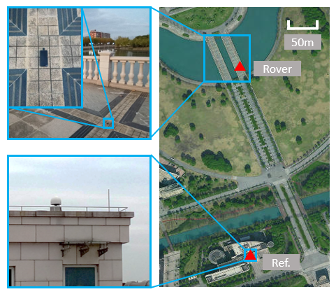
The experiment handheld platform is depicted in Fig 1. GNSS and ephemeris data were collected and processed by HUAWEI P10 which embedded a Broadcom BCM4774 chips. The GNSS antenna was installed in the upper of the phone, but the IMU model within P10 is unkown where the sampling rate of each inertial sensor was 50 Hz. A u-blox m8p receiver with South HY-BLRB02 Rantenna was simultaneously experimented as a comparison. The ground truth was marked by u-blox M8P RTK mode.
At about 9.5 km distance from the experiment area, one CORS network is available. This station was used as base-station of our real-time difference system.
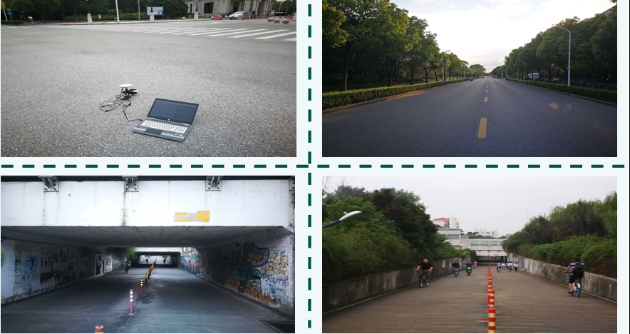
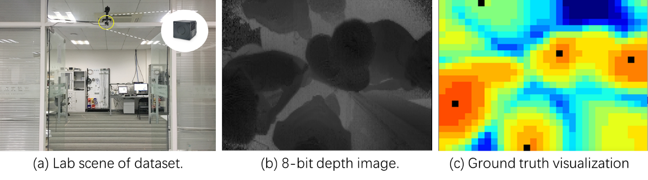
The experiments were carried out in the campus of SJTU with single point and IMU-assisted difference algorithm in different scenarios: static,kinematic, and signal blockage. The static was in the center of an open square, and the kinematic is a road in campus with the density trees(in fact these tree have effect on the devices.) but no buildings block satellite signal. Blockage scenario was choose in the tunnel as the picture three and four which will last 20meters distance in tunnel.
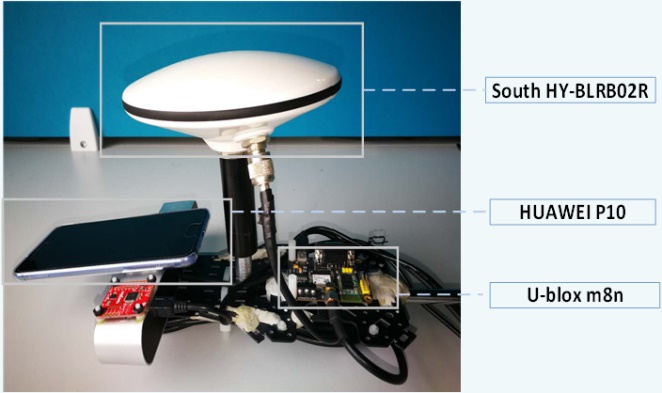
Fig. 1. The experiment handheld platform to collect data.
B. Data collection and processing
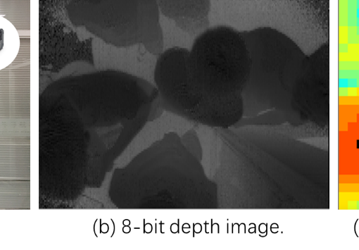
GNSS code measurements have been produced by GNSS chips in smartphone, but these available raw data should been transform into Rinex format file by means of Android operating system API which were elaborately described by Android developer documents. The mainly adopted classes are GnssMeasurement and GNSSClock which provided complete elements to generate Rinex format data such as pseudorange, carrier phase, Doppler and C/N0 The observables defined in Rinex format generation were depicted as Fig 2.
It is worth noting that the method getFullBiasNanos gets the difference between clock inside GPS receiver and the true GPS time since January 6, 1980. This value is available if the receiver has estimated the GPS time which was acquired by local crystal. However, the crystal oscillator existed a fixed linear clock drift due to manufacturing technology, resulting in an increase in the calculation of the bias(hundreds of nanoseconds per time which presented in Fig 3. So before GPS positioning, it is better to lock the initial effective value of the FullBiasNanos.
Fig. 3. The intermittent drift in smartphone GNSS clock
It is quite common knowledge that Android apps are written in Java. Java exists a drawback during the conversion between primitive type that it maybe generate a possible loss of precision. Float and double type are used to reduce storage space when storing rather than keeping high accuracy, frequent conversion data type operation may lead related time produce nanoscale bias which may lead several meters error in ultimate positioning result. Therefore, it is better avoiding to use float or double type to store data, conversion between different orders of magnitude, such as the order of seconds and nanoseconds, should be as much as possible concentrated in one operation during software calculation.
API level 24 also provides some Uncertainty method to get the error estimate of GNSS data, In order to increase the data accuracy and credibility, we set up some threshold by experience.
1\getPseudorangeRateUncertaintyMetersPerSecond()<10
2\getReceivedSvTimeUncertaintyNanos()<500
3\pseudorange value >1e7 & pseudorange<3e7
4\Satellite angle >15 degree & CNR >15 dB
5\Max position movement per epoch < 10m
Inertial sensors measurement were usually used to assist navigation system, Android operating system offered several efficient sensor API to output optimized data, for example, the method getRotationMatrixFromVector is to get the rotation matrix R transforming a vector from the device coordinate system to which is defined as a direct orthonormal basis the ENU(East North up) coordinate system.
SensorManager class also provides the sensor type: TYPE_LINEAR_ACCELERATION which can output a three dimensional vector indicating acceleration along each device axis, not including gravity.
The method registerListener registers a SensorEventListener for sensor at the given sampling frequency and the given maximum reporting latency. But the sampling frequency is only a hint to the system. Events may be received faster or slower than the specified rate. Usually events are received faster. So the rotation matrix R and acceleration A are most likely not on the same frequency and a consistent rate method is essential.
Additional error sources affecting GNSS observations were also accounted for, such as relativistic effects caused by the Earth’s rotation during signal propagation which results a dekameter-lever effect, and the satellite orbit eccentricity which results meter-level effect.
All positioning process were in the World Geodetic system 1984(WGS84) coordinate system. The real-time positioning results were converted into latitude and longitude, then mapped to Baidu LBS SDK.
IV. EXPERIMENT PERFORMANCE
The system test scheme was shown in Table 1 and reference solution was provided by u-blox m8p RTK model. Smartphone and u-blox m8n were installed together on the handheld platform.
Static:
The static point test was set in the open area for 5 minutes and the well meteorological condition made the number of visible satellite signal is well enough. Under this condition, the variance of PDD is only 4.2 meters, as opposed to 9 when using single KF model. 90% of the position errors are within 3.7 meters, this denotes that the system uncertainty is acceptable, u-blox m8n variance is 3.7m, which is close to PDD by smartphone.
Kinematic:
The kinematic test has been executed for approximately 400s long the middle of the road where the trees on both side are density but no buildings block satellite signal. The errors of PDD assisted by IMU, PDD without IMU and direct single point are shown in figure. The position curves proved that the PDD assisted by IMU performance exceeded two other model. The deviation and 90% error probability is better than static test, an empirical explanation is that random antenna movement would reduce the multiple-path influence which made the curve converge well.
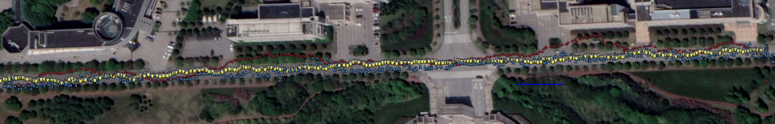
Fig. 3. The PDD kinematic result
The Height Error
The Horizonal Error
It is worthy to note that, the middle of test route is an open area where no trees planted on either side, the variance and result reflected on map also showed that this part apparently better than other part, which means the density trees had a bad effect on navigation signal. The best average solution was obtained by PPD with IMU assisted, the standard and standard also slightly degraded than PDD without IMU. Comparing the two PDD test results in open road condition, IMU function of fusion sheme is needless, as Doppler is the dominant factor in determining the forward direction.
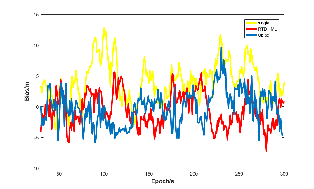
The comparative experiment results show that PDD can significantly improve the positioning accuracy, on open condition the deviation can be less than 3 meters. The contrast between horizontal with height error figures shows that the horizontal accuracy is apparently precise than height. In height error figure, the Ublox error curves shows more smoothly, and mean error is obviously below than the others, but the RTD+IMU performs no significant difference with single point which means the RTD+IMU is invalid to ameliorate height performance .
Blockage:
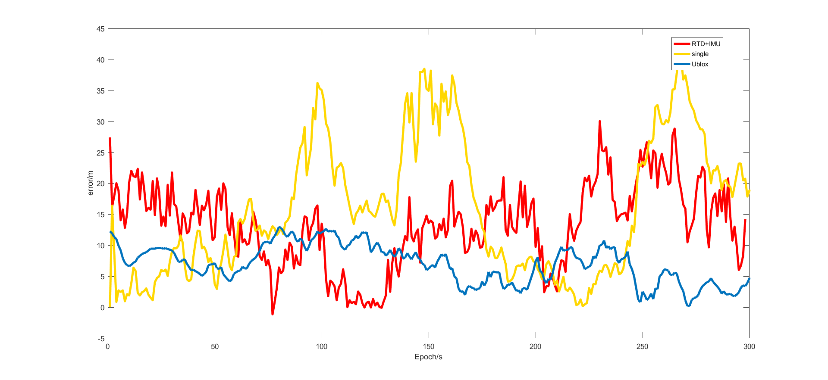
An experiment was also carried out to test the robustness when the GNSS signal was blocked, the scenario was chosen in campus tunnel , the road environment with 100 meters is worse than prior scene. In the middle of the road exist two short tunnel where the effective number after system selected of visible satellite was less than 4 and GNSS model could not independently afford right positioning information. As the result shows, the direct single point curve exists severe mutation curve, while RTD+IMU can slightly release the drastic drift and calibrate the fixed error. It demonstrates that MEMS-based IMU enable to assist GNSS but not sufficient for long time credibility.
Fig. 5. The PDD assisted by IMU performance when GNSS blocked
In our work, an experiment architecture was first introducedf and detailed the data collection and data processing. Then, PDD assisted by IMU model was presented and clarified the advantages than traditional solutions. To evaluate the system performance on smartphone, we performed in static, kinematic and signal blockage environment and compared with commercial u-blox m8n module. To mitigate external factors affect navi-information, the problems we met was analyzed IMU offered valid supplementary information in short time. We preliminary realize and verify the real-time high accuracy algorithm in the stand-alone smartphone platform using raw GNSS data. The comparative results show that PDD+IMU can effective increase the positioning accuracy.
.
