1 Introduciton
This dataset is specifically designed for evaluating visual-inertial based underwater localization method. It is collected in an artificial pool by a ZED2 Stereo Camera (with build-in IMU) with handmake waterproof measures. To make the dataset suitable for evaluating different VIO algorithms, different terrians were designed in the artifical pool and data in different trajectories were collected. The stereo camera is configured with 30 Hz capturing rate and 672×376 resolution, and the IMU is configured with 400 HZ capturing rate. The ground truth trajectories are obtained with the motion capture system at a rate of 150 Hz. Since the motion capture system was used, the accuracy of the ground truth can reach a millemeter-level. A sketch of the data collection enviroment is shown in Figure 1.
The dataset can download from https://pan.baidu.com/s/1NPcXUx7oJ8jh0JZtSdjjZA with extracting code batc.

Figure 1. A sketch of the data collection enviroment
2 Sensors specification

Figure 2.The specifications of the sensors
Figure 2 shows the specifications of the sensors used in the proposed dataset, for more details of the ZED2 stereo camera, you can visit https://www.stereolabs.com/zed-2/.
3 The acquisition system
A ZED2 Stereo camera with handmade waterproof measures is fixed to the bottom of a camera arm to collect the data, as shown in Figure 3. To obtain the ground truth trajectories, we fixed a set of IR-reflective markers on the top of the camera arm, and the other set of markers on the stereo camera. The motion capture system can provide 6D pose measurements of the 2 sets of markers. While collecting data, we hold the top of the camera arm and keep the steteo camera in the water.
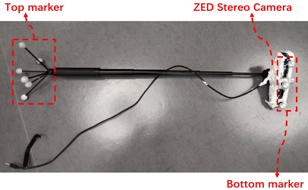
Figure 3: The acquisition system overview
4 The Coordinate System
Figure 4 provides a schematic view of the coordinate system, which uses the abbreviations shown in Table 1:
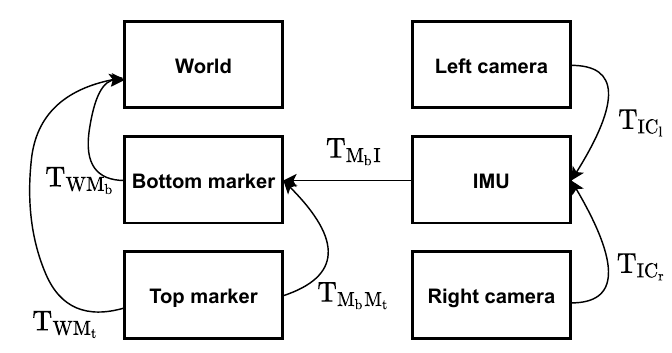
Figure 4: The schematic view of coordinate system
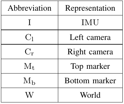
Table 1. The abbreviations used in coordinate systems.
5 Dataset overview
5.1 The data acquisition enviroment
The pool we used to collect data measures 4×2 metres. We divide it into 3 areas with different complexity of the texture as shown in Figure 5:
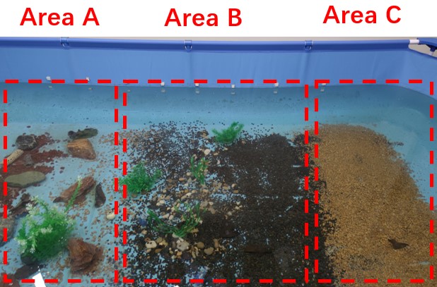
Figure 5 : The three areas of the data collection pool, different areas contain different level of texture.
Area A consists of large stones, area B consists of small stones and aquatic plants, area C only contains small stones. To make the dataset more challenging, data in 3 different shapes of trajectories are collected: rectangle, straight line and curve. A detailed description of the proposed dataset are shown in Table 2. It contains 10 sequences in total. Among all the sequences, 6 sequences are collected around the whole pool, 4 sequences are collected around single area.
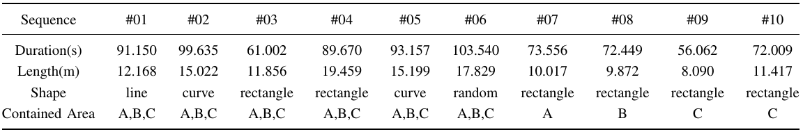
Table 2. The details of sequences in the proposed dataset
5.2 Dataset format
5.2.1 Dataset repository structure
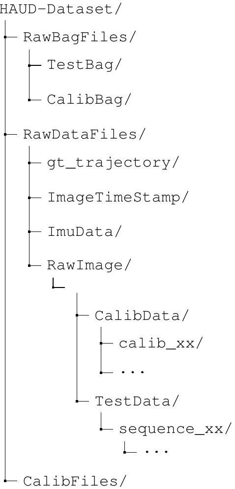
The dataset is available as ROS bag format and raw data format (e.g. raw images, CSV format IMU data, etc.), and the raw calibration sequences as well as the calibration result files are provided. The repository structure of the dataset is shown below:
5.2.2 File format
RawBagFiles/: this directory contains data in ROS bag format. The TestBag folder contains sequences for evaluation purpose, and the CalibBag folder contains sequences for calibration. The following topics contained in ROS bag files are used in the proposed dataset:
/vicon/camera/camera: the pose of the top marker expressed in world frame.
/vicon/zed2/zed2: the pose of the bottom marker expressed in world frame.
(Note: the pose of the top marker is only used to compute the transformation from the top marker to the bottom marker. While collecting test sequences, since the bottom marker is underwater, its pose is not visible, only the pose of the top marker is useful)
/zed2/zed_node/imu/data: the IMU measurements.
/zed2/zed_node/left_raw/image_raw_color: the left frame of the stereo camera.
/zed2/zed_node/right_raw/image_raw_color: the right frame of the stereo camera.
RawDataFiles/gt_trajectory: this directory contains the ground truth trajectories of each sequence, and each row in ground truth files contains quaternion-translation form pose in the follwing format:

Each pose describes a pose of the bottom marker expressed in world coordinate.
RawDataFiles/ImageTimestamp: this directory contains CSV format time stamp file of each image, each row of the CSV file has the following format:

(Note: since the left frame and the right frame of the stereo camera are hardware synchronized, only the left frame image name are listed in the image timestamp file)
RawDataFiles/ImuData: this directory contains CSV format IMU measurements, each row of the CSV file has the following format:

where ax indicates the angular acceleration measurements in x axis, lx indicates the linear acceleration measurements in x axis, and qx indicates the x component of quaternion-form orientation measurements.
RawDataFiles/RawImage: this folder contains raw images of each sequence. Each image is named in left/right_XXXXX.jpg format, where XXXXX indicates the number of the image, and left/right indicates the left frame or the right frame.
CalibFiles/: this folder contains the following calibration files:
calib_target_aprilgrid.yaml: the specifications of the aprilgrid calibration pattern used to calibrate the extrinsics between stereo camera and IMU, the format is the same as that of Kalibr.
calib_target_checkboard.yaml: the specifications of the checkboard calibration pattern used to calibrate the extrinsics of the stereo camera, the format is the same as that of Kalibr.
camera_calib.yaml: the intrinsic and the extrinsic of the stereo camera:
intrinsics:[fx,fy,cx,cy]
distortion_coeffs:[k1,k2,p1,p2], where k1 and k2 specify the radial distortion, p1 and p2 specify the tangent distortion.
camera_imu_calib.yaml: the extrinsic between camera and IMU. T_imu_cam0 represent the transformation from the left camera to IMU.
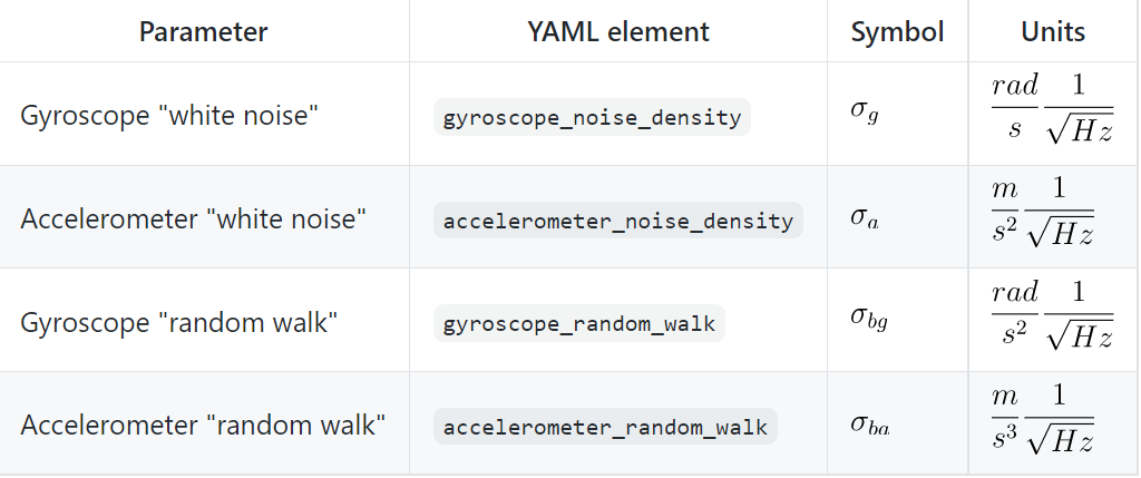
imu_calib.yaml: the intrinsics of the IMU. the unit is the same as that of Kaliba_allan:
marker_calib.yaml: the extrinsics between the top marker and the bottom marker. specify the rotation that brought the top marker coordinate to the bottom marker coordinate, and specify the translation (given in the top marker coordinate) that brought the top marker coordinate to the bottom coordinate. The format of the quartion is [w,x,y,z].
marker_imu_calib.yaml: the extrinsics between the bottom marker and IMU. and specify the quarternion and translation that brought the bottom marker coordiate to IMU coordinate respectively. The format of the quartion is [w,x,y,z].


